PDR Foundations: English sample
Six excerpts from the English manual, with the original lesson references and page numbers. The complete package contains seven PDFs and 235 pages. Practical training is sold separately.
This HTML edition includes the six-page excerpt and descriptions of its photographs. References to other lessons refer to the complete manual; they are not included in this excerpt.
Original manual page 1 of 113 / FM00
PDR Foundations
The Complete Illustrated Learning Pack
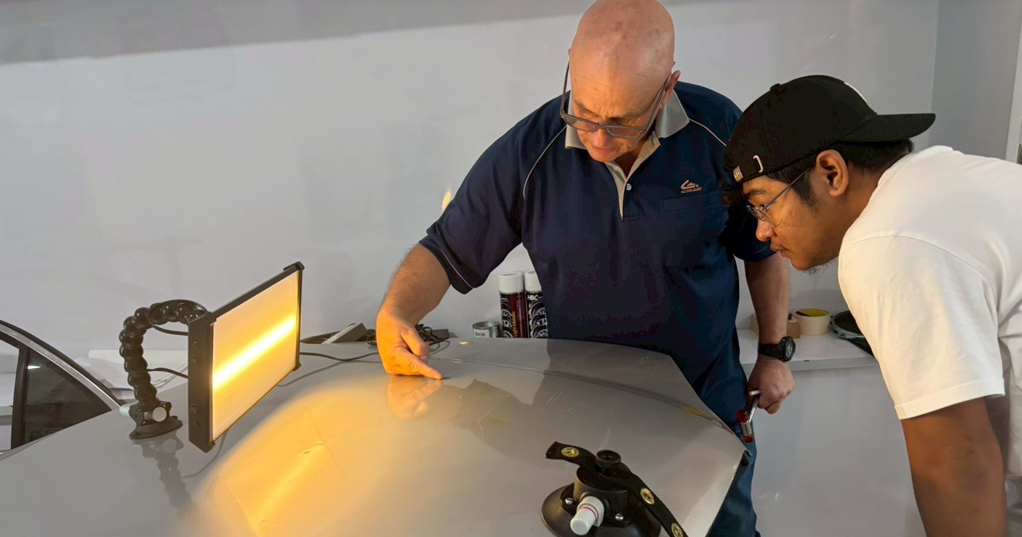
Photo-enhanced foundations manual
Sixteen modules · Real workshop photographs · Original technical diagrams
Forty-eight module checks · Fourteen dedicated photographic studies + matched photos across the manual · Working glossary
Understand the theory. Read the dent. Plan the repair. Practise with purpose. Use the companion workbook, casebook, reference cards, forms and explained assessment to apply the lessons.
Published by M&H Group Co., Ltd. / 2026 edition
US$35 one-time for the complete seven-PDF package. No videos. Equipment, individual coaching and technician certification are not included.
Original manual page 12 of 113 / M01.3
Choose your learning route
You can complete the theory route without buying tools.
Route A - theory and decisions
Read the manual in order. Reproduce the diagrams in your own words, complete the paper activities and explain the module checks before opening the answer guide. Use the casebook to compare alternative decisions. Complete the final knowledge assessment and return to the specific lessons behind any errors.
This route requires the PDFs, a way to read them and somewhere to write. Printing is optional. It does not require a vehicle, tools, a training panel or a paid external video. The core explanations, exercises and answers are included in the package.
Route B - supervised panel practice
Use the same theory route, then add the workbook with an experienced PDR trainer, suitable equipment and a secured, approved training panel. The trainer establishes the physical setup and confirms what is a high, low and acceptable intervention. Do not substitute a customer's car for a training panel.
The workbook describes observable gates rather than a calendar deadline. Repeat a session when you cannot identify the response or explain the next step. A pause or referral is a correct outcome when the conditions are uncertain.
Keep two records
Record knowledge separately from practical observation. “I can explain a high spot” and “I can locate and control one on this panel” are different statements. Do not merge them into a single completion tick. The workshop forms provide space for both your account and a trainer's observations; an empty trainer field is not approval.
Related manual references: M01 answers; High; Low.
Original manual page 25 of 113 / M04.1
Name the shape you are observing
A clear description comes before a repair pattern.
Low, high and crown
A low lies below the intended local surface profile. A high lies above it. A crown is a raised region associated with surrounding deformation; it need not be a neat, complete ring. These descriptions rely on a reference profile and observation, not on a universal rule about whether reflected stripes are close together.
The intended profile may already be curved. A vehicle panel is not necessarily meant to be flat. Compare the affected area with appropriate undamaged references and the component's designed shape. Do not remove a legitimate bodyline because it resembles a high under one view.
What you will learn
You will label known geometric features, record more than dent width, and separate what you can observe from what needs further evidence. That distinction prevents technical-sounding guesses from becoming instructions.
Use a map, not a label alone
A useful map records the visible low, any verified high or crown, the direction and extent of a crease, nearby panel features, access constraints and reference views. Mark uncertainty with a question rather than shading every surrounding area as a crown.
“Pressure zone” and “tension” are often used in workshop discussion. They can express a repairer's interpretation, but an uncalibrated reflection is not a stress measurement. For a beginner plan, write the observable geometry and the trainer's approved intervention rather than pretending the map gives a complete internal stress field.
Related manual references: M04 answers; Bodyline; Crease.
Original manual page 30 of 113 / M05.1
Your light is an observation system
The panel, light and eye work together.
What you are actually looking at
A glossy panel reflects a pattern from a light or board towards the observer. Changes in local surface orientation change which part of that pattern reaches the eye. For a simple reflected ray, the angle of reflection equals the angle of incidence, measured relative to the local surface normal. This geometric relationship is not a direct dent-depth scale.
The apparent pattern depends on the board, panel and viewpoint. Moving your head or the light can change the image even when the panel has not changed. A convincing before/after comparison therefore needs controlled viewing conditions.
What you will learn
You will explain the role of the three elements, establish a repeatable view, and use a cross-view to challenge an initial interpretation. You will also learn why a light/dark boundary must not automatically be called the deepest point.
Define your reference
Begin with a trainer-approved panel and an undamaged region whose intended shape is understood. Establish an orientation label, a comfortable eye position and a light/board position. Record enough detail to return to that arrangement. Keep the light secure; do not let it rest where tool input or a cable can move it.
Related manual references: M05 answers; Cross-view; Local surface normal.
Original manual page 93 of 113 / PS02 / Photo study 02 / References: M05.2-M05.5
The viewpoint is part of the setup
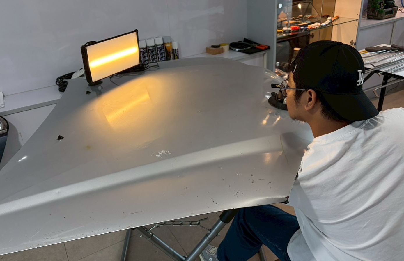
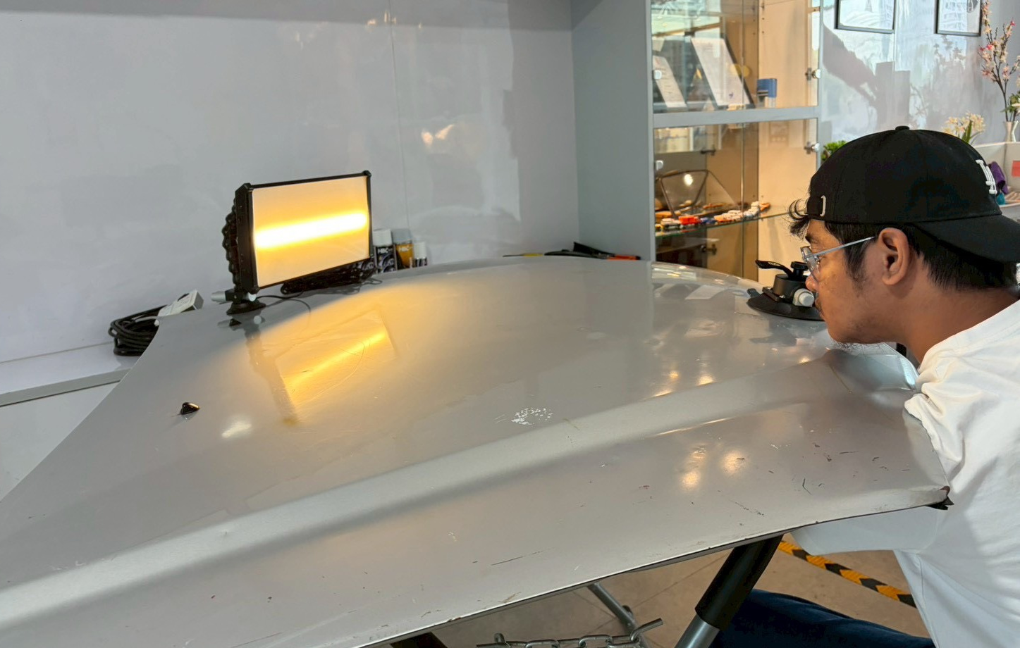
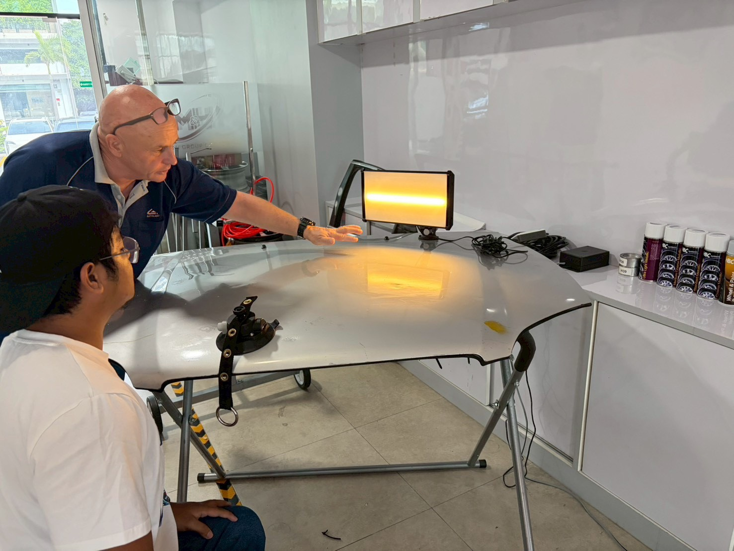
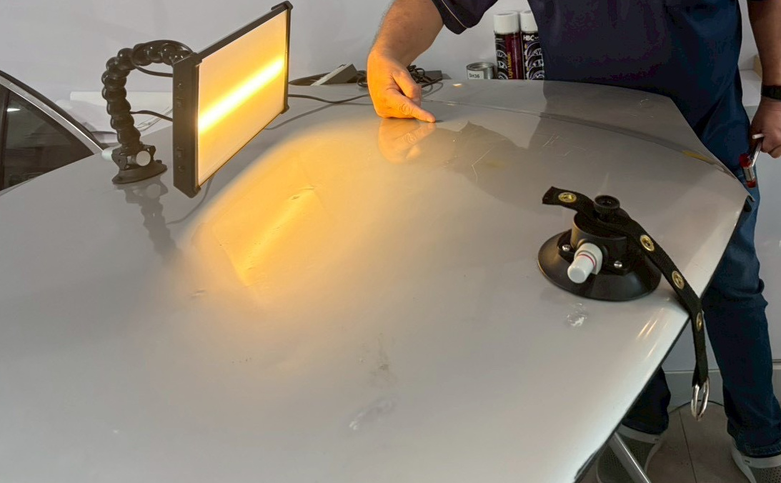
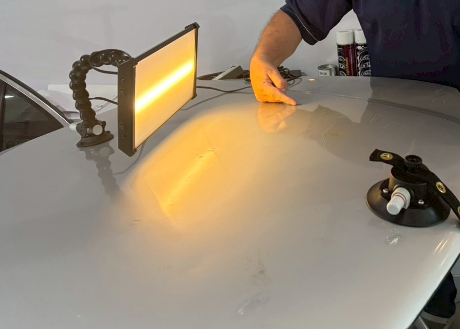
These are two actual training photographs, not a controlled before/after experiment. Their framing and observation geometry differ. The sequence and intervening work are not established by this pair.
What to notice
Compare the apparent width and position of the warm reflected band, the camera's view of the panel and the observer's position. Describe the visible differences without claiming that one panel is more repaired.
Build a valid comparison
For your own approved exercise, record the lamp position, observer position, panel orientation and stage. Compare the unloaded result from recoverable views. If a view changes, state the change rather than treating the pictures as equivalent.
Related manual reference: Lesson M05.2.
Original manual page 107 of 113 / G1
Working glossary
Alphabetical definitions and lesson links.
- A-B-A check
- Record baseline A, deliberately change one viewing variable for B, then restore A. It helps separate viewing effects from surface change.
Lesson M05
- Adhesion
- Attachment between materials, such as adhesive and tab/surface or a coating and its underlying system. Unknown coating adhesion cannot be assumed sound.
Lesson M12
- Alloy and temper
- An alloy has a specified combination of elements. Temper describes a processing condition, especially for aluminium, such as work hardening or heat treatment. The broad label “aluminium” does not establish either.
Lesson M03
- Backside protection
- Coatings and protection on the non-visible side that may require inspection or restoration after contact or access work.
Lesson M07; Lesson M14
- Blending
- A family of PDR techniques using controlled top-side impacts to influence surrounding shape or raised transitions. It may address a crown or refine the transition to the intended profile. Unlike repaint blending, it acts on panel geometry; the target and input still require skilled assessment.
Lesson M10
- Bodyline
- A designed panel feature that forms part of the intended geometry. Do not flatten it merely because it appears prominent in a reflection.
Lesson M04; Lesson M13
- Cavity wax
- A protective product used in specified locations and processes. Availability of a generic wax does not establish suitability for every vehicle.
Lesson M07
- Coating history
- What is known about the existing finish, previous work and inspection findings. Appearance alone does not establish the full history.
Lesson M03; Lesson M12