
 +66 88 984 8897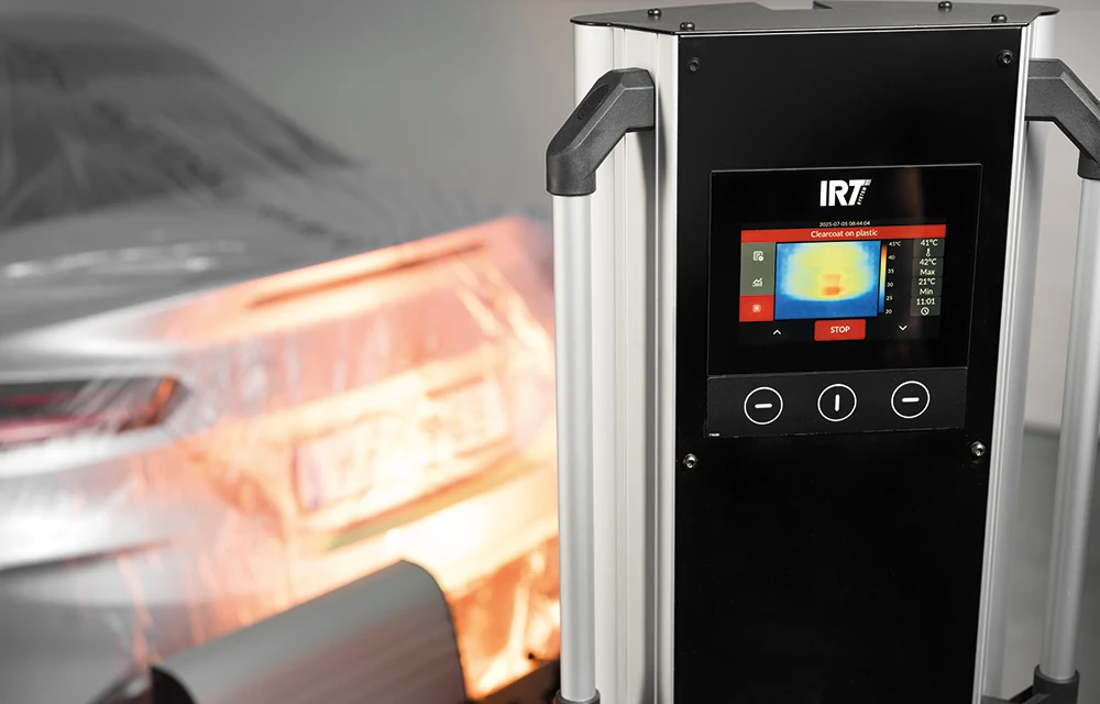
Temperature across the surface.
A 32 × 24 thermal sensor array measures 768 points. The controller follows the five hottest points and adjusts infrared output during the curing cycle.

IRT / HEDSON
Thermal-camera control. One cassette.
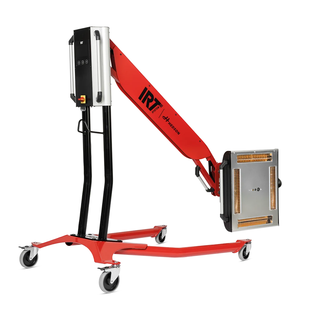
Single-cassette infrared curing with thermal-camera temperature control, radar distance guidance and a 1.1 × 1.5 m curing area.
IRT


YOUR WORKSHOP
Select the article for your required cassette arrangement and electrical supply. M&H can help compare the single- and twin-cassette models for your repair work.
| Article | Output | Supply | Connection | Frequency | Region |
|---|---|---|---|---|---|
| 801520 | 6 kW | 400 V · 3 PH | 5-pin | 50/60 Hz | EU |
| 801524 | 6 kW | 400 V · 3 PH | 4-pin | 50/60 Hz | EU |
| 801522 | 6 kW | 230 V · 3 PH | — | 50/60 Hz | EU |
| 801523 | 6 kW | 400 V · 3 PH | — | 50/60 Hz | AUS |
| 801525 | 6 kW | 200 V · 3 PH | 4P | 50/60 Hz | JP |
| 801526 | 6 kW | 230 V · 1 PH | — | 50/60 Hz | NA |
| 801527 | 6 kW | 230 V · 3 PH | — | 50/60 Hz | NA |
Your enquiry goes to M&H Group. No order or payment is placed here.
AT WORK
A 32 × 24 thermal sensor array measures 768 points. The controller follows the five hottest points and adjusts infrared output during the curing cycle.
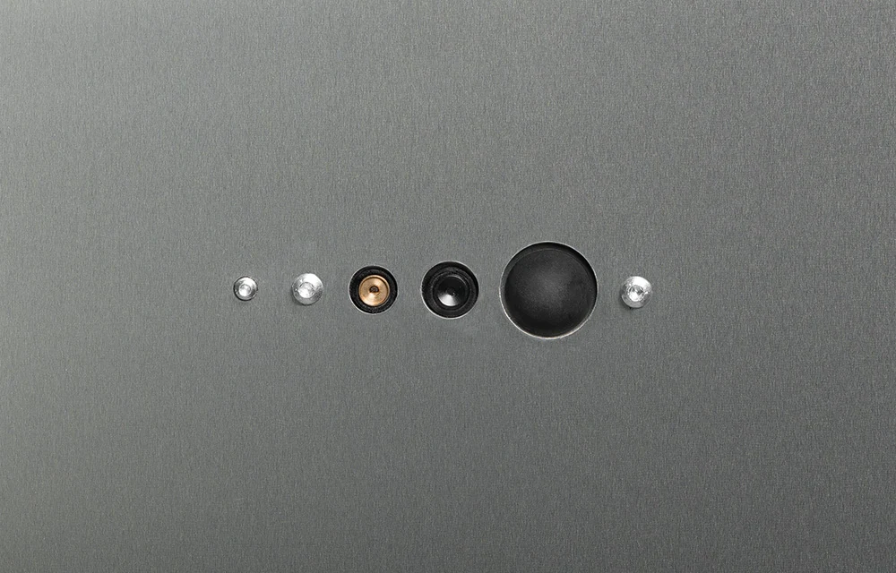
Radar distance guidance helps position the dryer. The display and an audible signal indicate when the selected distance is reached.
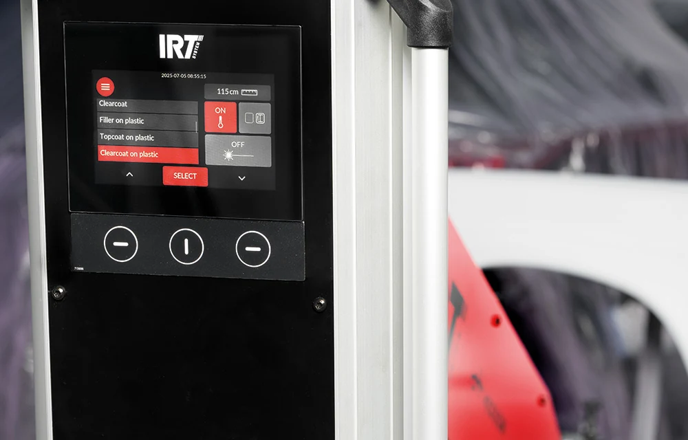
Touchscreen programmes cover putty, filler, basecoat, clearcoat and plastic work. Temperature profiles are logged, with process progress and energy use displayed.
TECHNICAL DETAILS
| Infrared output | 6 kW |
|---|---|
| Infrared cassettes | 1 |
| Curing area at 60 cm¹ | 1.1 × 1.5 m |
| Weight | 53 kg |
| Listed length² | 1,230 mm |
| Listed height² | 2,500 mm |
| Heating technology | Shortwave infrared |
| Infrared output | 6 kW |
|---|---|
| Infrared cassettes | 1 |
| Curing area at 60 cm¹ | 1.1 × 1.5 m |
| Weight | 53 kg |
| Listed length² | 1,230 mm |
| Listed height² | 2,500 mm |
| Heating technology | Shortwave infrared |
| Power source | Corded electrical supply |
| Installation | Floor mobile; not ceiling mounted |
| Handheld | No |
| Temperature measurement | Thermal camera |
| Distance guidance | Radar |
| Energy-use display | Yes |
| Application area | Preparation zone |
| Automated movement | No |
| Temperature control over time | Yes |
| Electrical configurations | 7 regional variants |
¹ Curing area measured at 60 cm on black sheet metal. Actual curing settings depend on the coating and substrate.
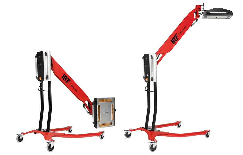
Thermal feedback supports process control; the coating specification, working distance and operating manual still determine the correct curing setup.
Select the article for your required cassette arrangement and electrical supply. M&H can help compare the single- and twin-cassette models for your repair work.
Discuss with M&H Sales →DOCUMENTS & SUPPORT
Speak with M&H about the selected article, installation, spare parts and operating instructions.
Ask M&H for product support →IRT TCR
Single-cassette infrared curing with thermal-camera temperature control, radar distance guidance and a 1.1 × 1.5 m curing area.
Product details →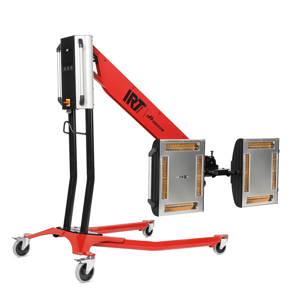
Twin-cassette infrared curing with thermal-camera temperature control, radar distance guidance and a 2.2 × 1.5 m curing area.
Product details →M&H GROUP / THAILAND & APAC